
Technical Guides · 2025-04-15
How to Wire REX-C100/C400/C700 Temperature Controllers with Relay and SSR Output
This blog provides a comprehensive guide on wiring REX series temperature controllers, including the C100, C400, and C700 models. It explains both relay and solid-state relay (SSR) output methods, sensor wiring (K-type and PT100), and alarm connections. Diagrams are provided for practical understanding and installation reference.
Temperature controllers like the REX-C series are commonly used in heating and cooling systems such as ovens, incubators, drying machines, and industrial heaters. Proper wiring ensures safe operation and accurate temperature control. This guide covers wiring methods for both relay output and solid-state relay (SSR) output versions of the REX-C100, REX-C400/C900, and REX-C700 models.
1. REX-C100 with Relay Output
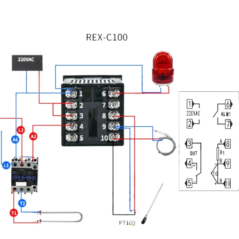
Wiring Highlights:
- Power Supply: AC 220V to terminals 1 & 2
- Output Control: Terminal 4 to relay/contactor coil
- Sensor:
- K-type thermocouple: terminals 9 & 10
- PT100 RTD: terminal 8 (red), terminals 9 & 10 (blue or black) - Alarm Output: Terminals 6 & 7
Use Case: Ideal for systems with mechanical contactors or low-power resistive loads.
2. REX-C100 with SSR Output
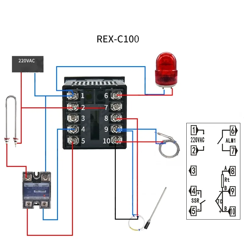
Wiring Highlights:
- Same power and sensor wiring as relay version
- Output Control: Terminals 4 (+) and 5 (–) connect to SSR control input
- SSR Output: Controls AC load circuit for heater
- Alarm Output: Terminals 6 & 7
Use Case: For higher-speed switching or resistive heating loads controlled via SSR.
3. REX-C400 / REX-C900 with Relay Output
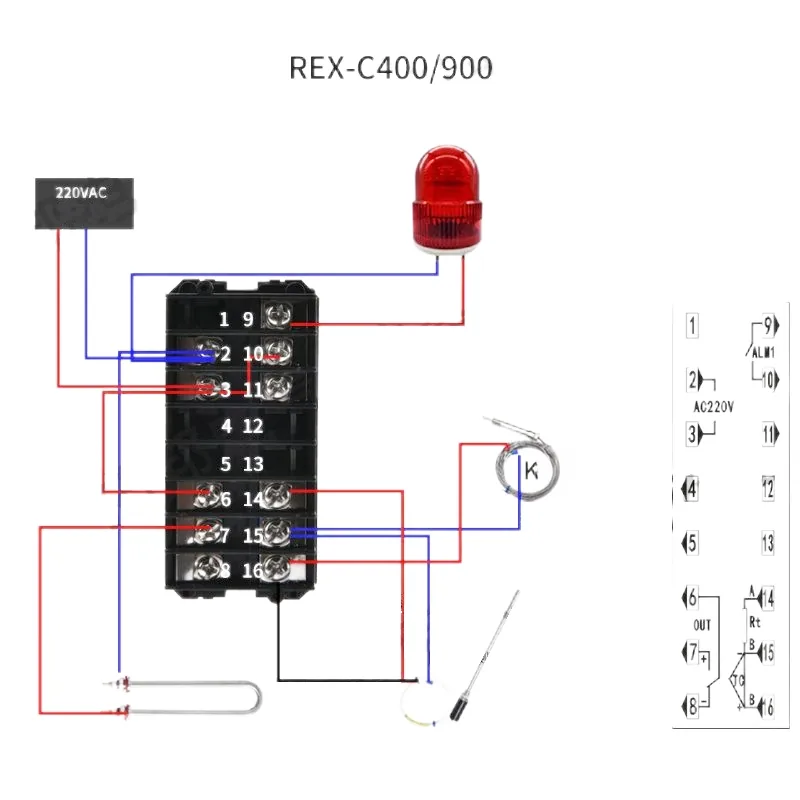
Wiring Highlights:
- Power Supply: Terminals 1 & 2
- Output Control: Terminal 4 → contactor
- Sensor:
- K-type: terminals 15 & 16
- PT100 RTD: terminal 14 (red), 15 & 16 (others) - Alarm Output: Terminals 9 & 10
Use Case: Best for mid-range power heating applications needing contactor control.
4. REX-C400 / REX-C900 with SSR Output
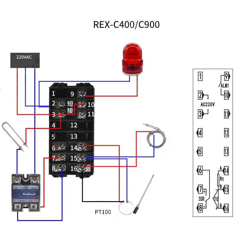
Wiring Highlights:
- Power Supply: Terminals 1 & 2
- Output Control: Terminal 6 (+), Terminal 7 (–) to SSR
- Sensor same as relay version
- SSR drives the heater directly
- Alarm Output: Terminals 9 & 10
Use Case: For loads >400W where contactless SSR switching is preferred.
5. REX-C700 with Relay Output
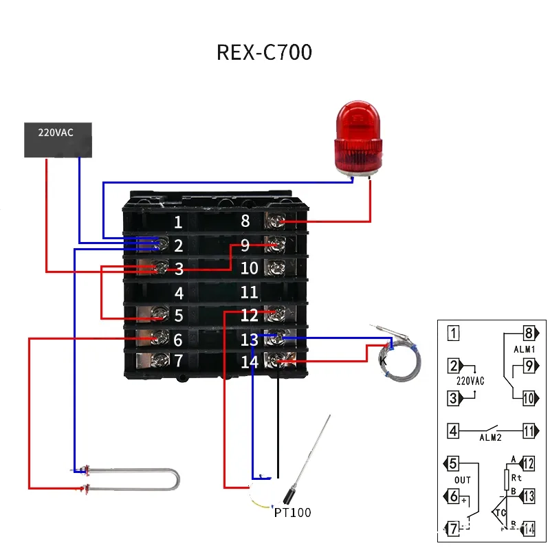
Wiring Highlights:
- Power: Terminals 1 & 2
- Output: Terminal 4
- Sensor:
- Thermocouple: 13 & 14
- PT100: 12 (red), 13 & 14 (blue/black) - Alarms: Terminals 8 & 9
Use Case: Industrial control for ovens, boilers, and temperature chambers.
6. REX-C700 with SSR Output
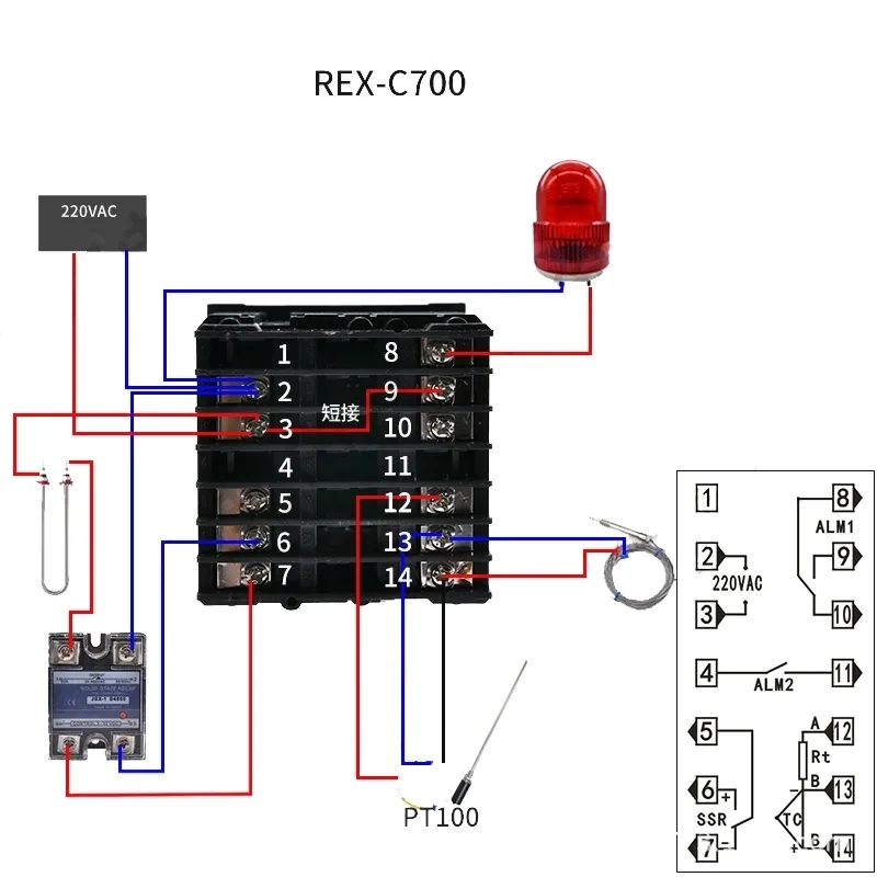
Wiring Highlights:
- Power Supply: Terminals 1 & 2
- Output: Terminals 6 (+) & 7 (–)
- Sensor: same as relay version
- Alarm Output: 8 & 9
Use Case: SSR switching for high-frequency operations with resistive loads.
Quick Tips for Installation
- Sensor types: Double-check if using K-type or PT100 and connect accordingly.
- SSR polarity: Ensure correct connection of SSR (+) and (–).
- Alarm Outputs: Connect to a buzzer or light as needed.
- Relay vs SSR: Use SSR for frequent switching, relay for inductive loads.
Example Wiring Diagrams
Each controller has a slightly different terminal layout. Refer to specific diagrams:
- ✅ REX-C100 Relay vs SSR
- ✅ REX-C400/900 Relay vs SSR
- ✅ REX-C700 Relay vs SSR
(Diagrams shown in full product manual and also available upon request)
Related Products
Conclusion
Wiring your temperature controller correctly ensures accurate control and safe operation. Whether using a relay or solid-state output, make sure to follow the terminal diagrams and double-check polarity and connections. Always choose the right controller model for your load type and application.
Need help selecting or wiring your controller? Contact our team at Beijing Strong Electric.