Technical Guides · 2025-04-06
SCR vs TRIAC: Differences, Circuit Topology and How to Choose
An engineering reference comparing SCRs and TRIACs for AC power control: conduction direction, circuit topology, triggering and commutation behavior, control methods, load compatibility, thermal and protection design, and a practical selection checklist.
SCRs and TRIACs are the two thyristor families most often compared when an AC power-control stage is specified. Both are gate-triggered semiconductor switches, but they conduct differently, integrate differently into a circuit, and suit different levels of power and robustness. This guide explains how each device works, where the real differences lie, and how to choose between them for industrial heating and power-control applications.
What Is an SCR?
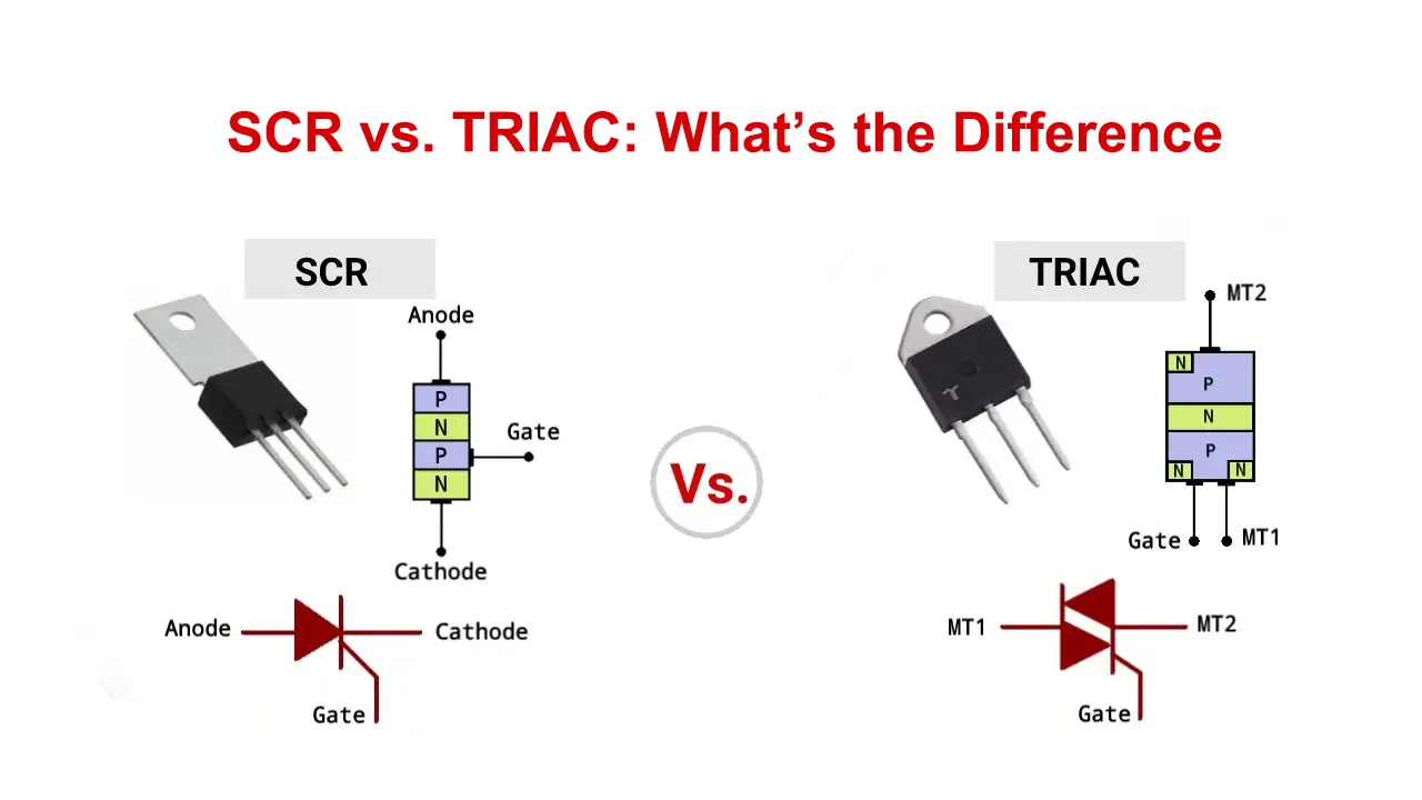
An SCR (Silicon Controlled Rectifier) is a unidirectional thyristor: once triggered by a gate pulse, it conducts current in one direction only and stays on until the current falls below its holding level. In AC circuits, a single SCR therefore controls only one half-cycle. Full-wave AC control with SCRs is normally built from two SCRs connected in anti-parallel — one for each half-cycle — either as discrete devices or inside a packaged SCR power module.
- High blocking-voltage and current ratings are widely available, including stud, capsule and module packages.
- Well-defined turn-off: each SCR commutates naturally when its half-cycle current crosses zero.
- Common inside industrial voltage regulators, rectifier bridges and high-power controllers.
What Is a TRIAC?
A TRIAC (Triode for Alternating Current) is a single bidirectional device. With one gate it can be triggered into conduction on both the positive and the negative half-cycles, so one TRIAC alone can control the full AC waveform. This integration makes TRIACs compact and convenient for lower-power AC switching and phase control.
- One device controls both half-cycles — simpler, smaller circuitry.
- Because current reverses through the same die, turn-off at each zero-crossing (commutation) is more demanding, especially with inductive loads where voltage and current are out of phase.
- Typical of light dimmers, fan controls, appliance regulators and small solid state relays.
SCR vs TRIAC: Key Differences at a Glance
| Aspect | SCR | TRIAC |
|---|---|---|
| Current direction | Unidirectional — conducts one polarity only | Bidirectional — conducts both AC half-cycles |
| AC circuit topology | Two devices in anti-parallel (or an SCR module) for full-wave control | One device controls the full AC waveform |
| Gate triggering | One gate per device; triggered on its forward half-cycle | Single gate; triggerable on both half-cycles (multiple quadrants) |
| Commutation behavior | Each SCR sees a clean current zero-crossing every half-cycle and turns off naturally | Must commutate while current reverses through the same die; more sensitive to rate of voltage rise (dv/dt) with inductive loads |
| Surge and robustness considerations | High surge and thermal ratings available, particularly in module packages with large junction area and direct heat-sink mounting | Compact die; robustness depends on the specific rating, gate drive and snubber design rather than the device class itself |
| Typical integration | Power modules, voltage regulators, rectifier and regulator bridges | Compact controllers, small SSRs, appliance and lighting control |
| Common applications | Industrial heating regulation, transformer-coupled loads, high-power AC/DC control | Light-duty AC switching, lamp and fan control, small resistive heaters |
Single TRIAC vs Two Anti-parallel SCRs
Functionally, a TRIAC and a pair of anti-parallel SCRs both deliver full-wave AC control, and the choice between them is an engineering trade-off rather than a rule:
- Simplicity and size: a TRIAC replaces two devices, two heat-sink interfaces and two gate circuits with one part.
- Thermal design: an anti-parallel SCR pair spreads the losses across two dies, which can ease heat-sinking at higher currents.
- Commutation margin: with inductive or phase-shifted loads, each SCR in a pair recovers while the other conducts, which generally gives more dv/dt margin than a single TRIAC of comparable rating.
- Availability: at higher voltage and current classes, SCR modules cover ratings where equivalent single TRIACs are uncommon.
Phase-angle vs Zero-cross and Burst Control
Phase-angle control, zero-cross switching and burst (cycle) control are triggering methods, not device properties. Both SCR pairs and TRIACs can be driven in any of these ways; what changes is the firing electronics:
- Phase-angle control delays the gate pulse within each half-cycle to vary the effective output voltage continuously. It suits loads that need smooth power regulation and is the usual mode of SCR voltage regulators.
- Zero-cross switching turns the device on only near the voltage zero-crossing, reducing switching noise and inrush stress. It is the standard mode of most zero-cross solid state relays.
- Burst / cycle control passes or blocks whole groups of cycles to proportion average power — common for resistance heating where the thermal mass smooths the output.
Load Compatibility
- Resistive heating (cartridge, band, infrared heaters): the most forgiving load. Both device families handle it well; the choice is driven by current level, control method and cooling rather than device type.
- Inductive loads (motors, coils): current lags voltage, so the device must commutate against a recovering voltage. Gate drive, snubber networks and dv/dt rating matter more here, and anti-parallel SCR pairs are often preferred at higher power.
- Transformer-coupled loads: inrush on energization and possible core saturation should be evaluated; confirm the controller and semiconductor ratings against the actual inrush profile rather than nameplate current alone.
- Special heating elements such as silicon carbide or molybdenum disilicide have resistance that changes strongly with temperature and age; size the power stage from the element manufacturer’s data and measure the real current range before finalizing the selection.
Thermal, Surge and Protection Considerations
- Derating: a device’s rated voltage and current are maximum limits, not recommended operating points. Select ratings with margin for ambient temperature, enclosure conditions and load behavior.
- Heat-sinking: conduction losses are roughly proportional to load current. Modules and SSRs above a few amperes generally need a correctly sized heat sink with thermal interface material and adequate airflow.
- dv/dt and di/dt: fast voltage rise can re-trigger a device after commutation, and excessive current rise at turn-on can damage the junction. Snubber networks and proper gate drive address both.
- Protection: protect the power stage against short circuits and overcurrent with devices coordinated to the semiconductor’s surge rating, and against voltage transients where the installation requires it.
Safety note: always wire with the power disconnected and verify isolation before touching terminals. The voltage and current printed on a device are its absolute ratings — the safe working values of a real system depend on derating, heat-sinking and protection, and must be engineered, not assumed. Any energized measurement or live test must be carried out by qualified personnel only.
Selection Checklist
- Confirm the real load: type (resistive / inductive / transformer-coupled), steady current, inrush and operating voltage.
- Decide the control method first — on/off, zero-cross, burst or phase-angle — since it determines the firing electronics, not the device family.
- For full-wave AC, choose the topology: one TRIAC for compact lower-power designs, or anti-parallel SCRs / an SCR module where thermal margin, surge capability or commutation robustness dominate.
- Check dv/dt, di/dt and surge ratings against the actual load and supply conditions.
- Size the heat sink from worst-case current and maximum ambient temperature inside the enclosure.
- Consider a complete module or solid state relay instead of bare semiconductors when isolation, trigger circuitry and protection should come integrated.
Common Misconceptions
- “TRIACs are only for loads below about 40 A and SCRs above.” There is no fixed current boundary between the families. The choice depends on the specific device or module ratings, surge capability, dv/dt and di/dt limits, cooling, load type, environment and circuit topology.
- “Zero-cross control means a TRIAC; phase-angle control means an SCR.” Both are triggering methods that either family can use.
- “An SSR is just a TRIAC.” A solid state relay is a complete switching module with isolation and drive circuitry; internally it may use a TRIAC or anti-parallel SCRs, depending on its design and rating.
- “A higher nameplate current is always safe enough.” Nameplate ratings are not working values; derating, cooling and protection decide real reliability.
FAQ
Can a single SCR control an AC load?
Only one half-cycle. Full-wave AC control needs two SCRs in anti-parallel, an SCR module, or a TRIAC.
Is a TRIAC better than two SCRs?
Neither is universally better. A TRIAC is simpler and more compact; an anti-parallel SCR pair generally offers more thermal and commutation margin at higher power. Choose from the load, control method and cooling conditions.
Do zero-cross SSRs always contain TRIACs?
No. Zero-cross describes when the relay turns on, not what is inside it. Manufacturers use TRIACs or anti-parallel SCRs depending on the rating.
Which device should I choose for a resistive heater?
Both families work well on resistive loads. Base the decision on load current, required control method, available panel cooling and whether you want a bare semiconductor or an integrated module such as an SSR or SCR regulator.
Related Products
- BDTY Single Phase SCR Voltage Regulator
- BSTY Three Phase SCR Voltage Regulator
- SCR3L Three Phase SCR Voltage Regulator
- SSR-LA Analog Controlled Solid State Relay
- Solid State Relays & SCR Power Modules
Need Help Selecting a Power-Control Solution?
Beijing Strong Electric manufactures SCR voltage regulators, solid state relays and the temperature controllers and sensors that complete a control loop. Tell us your load type, current and control method and our engineers will recommend a matched solution — contact us for selection support and a quotation.