
Product Updates · 2026-03-24
TC5-S PID Temperature Controller: Model Code, Terminals, Outputs and Commissioning
A working reference for the TC5-S 1/16 DIN digital PID temperature controller: how to read the model code, the electrical specification, terminal-by-terminal wiring, how to choose between relay, SSR drive and 4-20mA output, and the checks to run before the first heat-up.
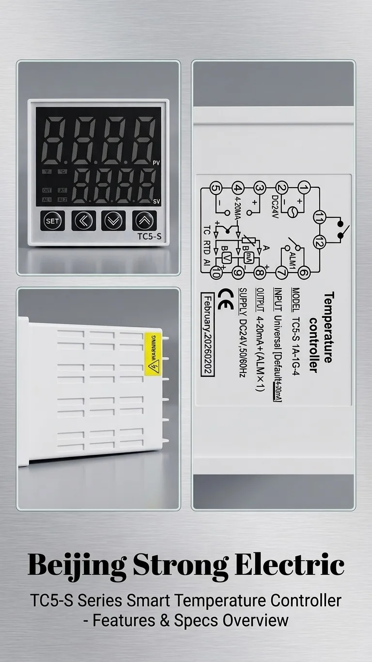
The TC5-S is the 48 × 48 mm (1/16 DIN) member of the TC5 series digital PID temperature controller family. This page is a working reference for specifying, wiring and commissioning it. It covers the model code, electrical data, terminal assignment, output selection and the checks to run before the first heat-up.
1. Model code
The code on the housing label reads TC5-S input-output-supply. The unit photographed above is a TC5-S 1A-1G-4.
| Field | Meaning |
| TC5-S | 48 × 48 mm panel cut-out 45 × 45 mm, dual LED display (white PV / green SV) |
| Input group | Universal input: K, E, J, T, R, S thermocouple, Pt100 / Cu50 RTD, or analog 4–20 mA / 0–10 V |
| Output group | Relay contact, SSR drive pulse, or 4–20 mA continuous output |
| Supply | Code 4 = DC 24 V; AC 100–240 V versions are also produced |
Confirm the input and output codes when ordering: the input type is a parameter setting, but the output hardware and the supply voltage are fixed at build time and cannot be changed in the field.
2. Technical specification
| Parameter | Specification |
| Display | Dual 4-digit LED, PV (white) and SV (green) |
| Display accuracy | ±0.5% FS ±1 digit |
| Sampling | Approx. 100 ms |
| Control | PID with auto-tune, or ON/OFF selectable by parameter |
| Main output | Relay contact / SSR drive / 4–20 mA (per model code) |
| Alarm output | ALM1 relay contact, deviation or absolute alarm |
| Supply | DC 24 V or AC 100–240 V, 50/60 Hz |
| Panel size | 48 × 48 mm, cut-out 45 × 45 mm |
| Compliance | CE |
3. Terminal assignment
- 1, 2 — power supply. DC 24 V on the -4 supply code. Check the label before energising: applying AC 220 V to a 24 V unit destroys it immediately.
- 3, 4 — main control output. On the 4–20 mA version this pair feeds the SCR power regulator or control valve; observe polarity.
- 6, 7 — alarm relay contact. Volt-free contact for a beacon or interlock.
- 8, 9, 10 — sensor input. Thermocouple on two terminals; 3-wire Pt100 uses all three, with the single-coloured lead on the dedicated compensation terminal.
4. Choosing the output type
| Output | Use it when |
| Relay contact | Slow thermal masses switched through an AC contactor. Cheapest option, no panel heat, but contacts wear at short cycle times. |
| SSR drive | Fast zones — sealing bars, extruder barrels, hot runners. Drives a DC-input SSR-DA solid state relay with a 3–32 VDC control range. |
| 4–20 mA | Continuous power modulation through an SCR voltage regulator, or a modulating valve. Removes the sawtooth ripple of on/off cycling. |
5. Sizing the power stage
- Rate the switching device at roughly twice the steady-state load current: a 20 A heater bank takes a 40 A SSR or SCR module.
- An SSR dissipates about 1–1.5 W per ampere, so 20 A adds 20–30 W inside the cabinet. Fit a matched SSR heat sink with thermal paste and vertical fins.
- For 4–20 mA control, verify the regulator input impedance keeps the loop inside the controller compliance voltage; do not put two 4–20 mA loads in series without checking.
6. Commissioning checklist
- Supply voltage on terminals 1 and 2 matches the label code.
- Input-type parameter matches the fitted probe — a K-type probe read as Pt100 looks plausible cold and is badly wrong hot.
- Thermocouple polarity verified: the PV rises as the process heats. A falling reading means the two sensor wires are reversed.
- Output-type parameter matches the wiring actually installed; one output method only.
- Setpoint upper limit and alarm setpoint set below the safe limit of the machine.
- PID auto-tune run at normal process temperature with the real load in place, not on an empty machine.
- Sensor and 4–20 mA wiring routed away from the AC load cables to avoid induced noise.
7. FAQ
Can the TC5-S accept a Pt100 sensor?
Yes. The universal input covers Pt100 and Cu50 RTDs as well as K, E, J, T, R and S thermocouples. Change the input-type parameter and, for a decimal display, the range and decimal-point parameters — the procedure is in the TC5 Pt100 decimal and range setup guide.
What is the difference between TC5-S and the larger TC5 models?
Panel size and terminal count only. Firmware, parameter set and accuracy are shared across the series; see the TC5 series product page for the full size table.
Why choose 4–20 mA output over SSR drive?
SSR drive cycles the load on and off within a time-proportioning window. A 4–20 mA output feeding an SCR regulator varies the delivered power continuously, which suits loads sensitive to thermal cycling such as quartz and infrared heaters.
Is an external safety thermostat still required?
Yes. The ALM1 relay is a process alarm, not a safety device. Machine safety requires an independent hardwired over-temperature cut-out.
Technical support
Beijing Strong Electric manufactures PID temperature controllers, solid state relays and SCR power modules and thermocouple and RTD sensors. For model selection email sales@strong-ele.com.