
Product Updates · 2025-04-11
TCN4 Series PID Temperature Controller: Model Codes, Inputs, Outputs and Commissioning
A working reference for engineers specifying or commissioning a TCN4 series digital PID temperature controller: how the four panel sizes differ, which sensor inputs are accepted, when to use the relay output with a contactor versus the SSR drive output, and the checks to run before first heat-up.
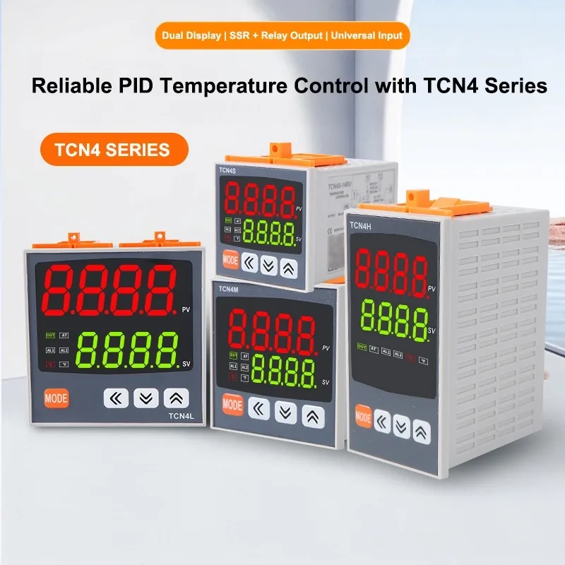
The TCN4 series is a panel-mount digital PID temperature controller used on ovens, extruders, blow moulding machines and packaging lines. This page is a working reference for selecting the right model, wiring it correctly and commissioning it. Full model data is on the TCN4 product page.
1. Panel sizes and model codes
All four variants share the same firmware and parameter set; they differ only in bezel size and terminal layout.
| Parameter | Specification |
| TCN4S | 48 × 48mm panel, 12 terminals — the compact retrofit size |
| TCN4H | 48 × 96mm vertical panel, 14 terminals |
| TCN4L | 96 × 48mm horizontal panel with large digits, 14 terminals |
| TCN4M | 72 × 72mm panel, 14 terminals |
Terminal numbering differs between the 12-terminal TCN4S and the 14-terminal H/L/M bodies, so always identify the model on the housing label before wiring. Terminal-by-terminal diagrams for both layouts are in the TCN4 contactor and SSR wiring guide.
2. Sensor input
The input type is a parameter setting, not a hardware option, so one controller can be moved between thermocouple and RTD sensors. Supported inputs include K, E, J, T, R and S thermocouples plus Pt100 and Cu50 RTDs.
- Thermocouple: two wires only. Reversed polarity makes the reading fall as the process heats — the classic symptom of a swapped blue and red wire.
- 3-wire Pt100 / Cu50: the single red wire goes to the dedicated compensation terminal; the remaining two wires can be fitted in either order.
- Set the input-type parameter to match the fitted probe before the first heat-up. A K-type reading on a Pt100 setting will look plausible at room temperature and badly wrong at process temperature.
- Use compensating cable of the same type as the thermocouple for extension runs; ordinary copper wire introduces a junction error.
Sensor options and mounting styles are listed under temperature sensors.
3. Control output: relay or SSR drive
The -14RV models carry both a relay contact output and an SSR drive output on separate terminals. Only one may be used at a time, and the output-type parameter must match the wiring actually installed.
| Parameter | Specification |
| Relay contact output | Switches a contactor coil or a small load directly. Mechanical contacts wear, so cycle times are long. Use an AC contactor once the load exceeds roughly 1000 W. |
| SSR drive output | A low-voltage DC pulse that drives a solid state relay such as the BSSR-25DA. No moving parts, fast cycling, tighter control around setpoint. |
| Alarm output | A separate relay contact for over-temperature beacons or interlocks; it is not a substitute for a hardwired safety thermostat. |
4. Choosing between contactor and SSR
- Slow thermal masses with long cycle times — kilns, large tanks: relay output plus an AC contactor is cheaper and produces no panel heat.
- Fast, tightly controlled zones — extruder barrels, sealing bars, hot runners: SSR output, because contactor life becomes the limiting factor at short cycle times.
- An SSR dissipates roughly 1 to 1.5 W per ampere of load current, so a 25 A zone adds 25–38 W of heat inside the cabinet. Fit a matched SSR heat sink with thermal paste and vertical fins.
5. Commissioning checklist
- Supply is connected to the power terminals only; the relay short link is fitted for the correct model.
- One output method is wired — never both relay and SSR.
- Input-type parameter matches the fitted sensor; output-type parameter matches the wiring.
- Sensor polarity verified: the process value rises when the load is heated.
- Setpoint limit and alarm setpoint configured below the safe limit of the machine.
- PID auto-tune run at normal process temperature with the real load present, not on an empty machine.
- SSR mounted on a heat sink; DC control wiring routed away from AC load wiring.
6. FAQ
Can I use the relay output and the SSR output at the same time?
No. Both are present on the terminal block, but the controller drives one output method only. Wire one and select the matching output type in the parameters.
When is an AC contactor required?
Once the heating load exceeds about 1000 W. The controller relay then switches only the contactor coil and the contactor main contacts carry the heater current.
The display rises when the process cools. What is wrong?
Thermocouple polarity is reversed. Swap the two sensor wires and confirm the reading tracks the process upward.
Which SSR pairs with a TCN4?
A DC-input SSR whose control range covers the controller drive voltage — for example the SSR-DA series with a 3–32 VDC input — sized at roughly twice the steady-state load current.
Technical support
Beijing Strong Electric manufactures PID temperature controllers, solid state relays and SCR power modules and thermocouple and RTD sensors. For selection help email sales@strong-ele.com.