
Technical Guides · 2026-08-27
How to Wire CH102, CH402, CH702 and CH902 PID Temperature Controllers
A practical wiring guide for CH102, CH402, CH702 and CH902 PID temperature controllers, covering power, AC contactor and SSR control, thermocouple and Pt100 sensors, alarms and commissioning.
The CH Series is a family of panel-mounted PID temperature controllers for industrial heating equipment. CH102, CH402, CH702 and CH902 use the same basic control principles in different panel sizes, but their terminal layouts are not identical. Identifying the model before wiring is therefore essential.
This guide explains the connections shown in the supplied diagrams for controller power, relay output with an AC contactor, SSR drive output, thermocouple or Pt100 input, and alarm outputs. It also provides a safe commissioning sequence and practical troubleshooting checks.
Important: Wiring must be completed by a qualified electrician with all supplies isolated, locked out and verified dead. Check the full model code, label and diagram supplied with the controller before installation. Product options and production revisions may use different terminal assignments. The markings on the actual controller take priority over this guide.
CH Series models covered in this guide
| Model | Panel size | Terminal layout used here |
| CH102 | 48 × 48 mm | 12 terminals |
| CH402 | 48 × 96 mm | 12 terminals |
| CH702 | 72 × 72 mm | 18 positions |
| CH902 | 96 × 96 mm | Same 12-terminal diagram as CH402 |
The wider CH502 is part of the CH Series but is not covered by the three wiring diagrams on this page. Use the diagram supplied with a CH502 rather than assuming another model’s terminal numbers.
Before wiring
- Isolate the controller supply and the heater power circuit, then verify the absence of voltage.
- Read the complete model code and confirm whether the unit has relay output, SSR drive output, or another option.
- Confirm the controller supply voltage from its label. The standard product range is commonly specified for 100–240 VAC, but the individual unit label is authoritative.
- Confirm the configured sensor type and its polarity or lead arrangement.
- Choose either the relay/contactor method or the SSR method that matches the controller output. Do not treat them as interchangeable.
- Size the contactor or SSR for the heater voltage, current, load type and switching duty. Provide suitable overcurrent protection and protective earthing.
- Keep low-level sensor wiring separated from mains, heater and contactor conductors. Cross power cables at right angles when separation cannot be maintained.
- Fit the controller in an enclosure so energized terminals cannot be touched.
Terminal summary
CH102, CH402 and CH902
| Function | Terminal(s) | Connection shown |
| Controller power | 1 and 2 | AC supply; confirm voltage on the product label |
| SSR drive | 3 (–), 4 (+) | Connect to the control input of a compatible DC-input SSR |
| Relay control output OUT1 | 5 and 6 | Voltage-free contact used to switch an external circuit, typically a contactor coil |
| Alarm 2 | 7 and common 9 | Alarm contact; function depends on alarm settings |
| Alarm 1 | 8 and common 9 | Alarm contact; function depends on alarm settings |
| Pt100 RTD | 10, 11 and 12 | Three-wire RTD connection |
| Thermocouple | 11 (+), 12 (–) | Observe thermocouple polarity |
CH702
| Function | Terminal(s) | Connection shown |
| Controller power | 1 and 2 | AC supply; confirm voltage on the product label |
| SSR drive | 3 (–), 4 (+) | Connect to the control input of a compatible DC-input SSR |
| Relay control output OUT1 | 5 and 6 | Voltage-free contact used to switch an external circuit |
| Alarm 2 | 10 and common 12 | Alarm contact; function depends on alarm settings |
| Alarm 1 | 11 and common 12 | Alarm contact; function depends on alarm settings |
| Pt100 RTD | 16, 17 and 18 | Three-wire RTD connection |
| Thermocouple | 17 (+), 18 (–) | Observe thermocouple polarity |
Unused terminal positions on the CH702 must remain unconnected unless the label and manual for the exact model state otherwise.
CH102 wiring diagram
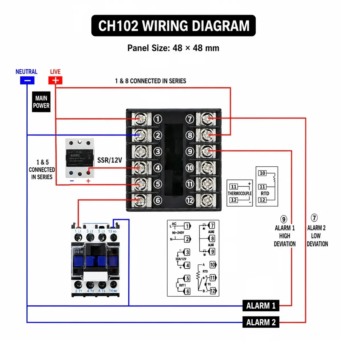
The CH102 uses terminals 1 and 2 for controller power. For an SSR-output unit, terminals 3 and 4 provide the polarized drive signal: terminal 3 is negative and terminal 4 is positive. For a relay-output unit, OUT1 is the dry contact across terminals 5 and 6.
The sensor input is at the opposite end of the terminal block. A thermocouple connects to 11 (+) and 12 (–). A three-wire Pt100 uses terminals 10, 11 and 12. Alarm 1 and Alarm 2 share terminal 9 as their common terminal in the illustrated layout.
CH402 and CH902 wiring diagram
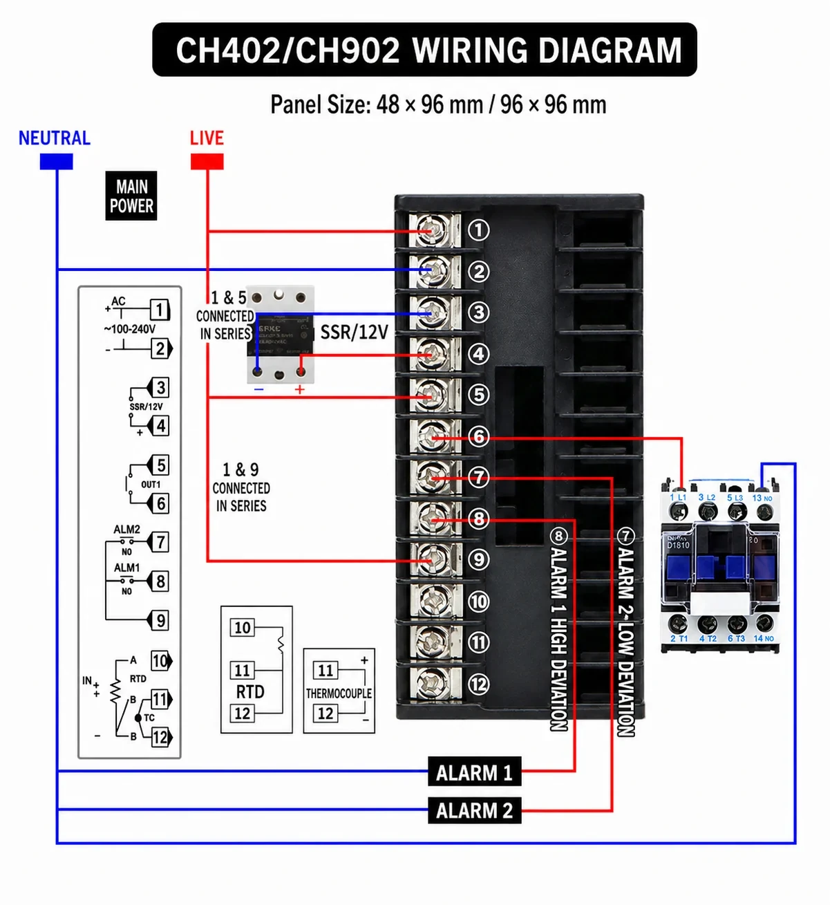
CH402 and CH902 share the 12-terminal arrangement shown above. The electrical functions match the CH102 terminal summary, although the enclosure and panel dimensions are different.
Do not select the wiring method from the front-panel size alone. Check the output code on the controller label to determine whether terminals 3–4 are the active SSR drive output or terminals 5–6 are the active relay output for the ordered version.
CH702 wiring diagram
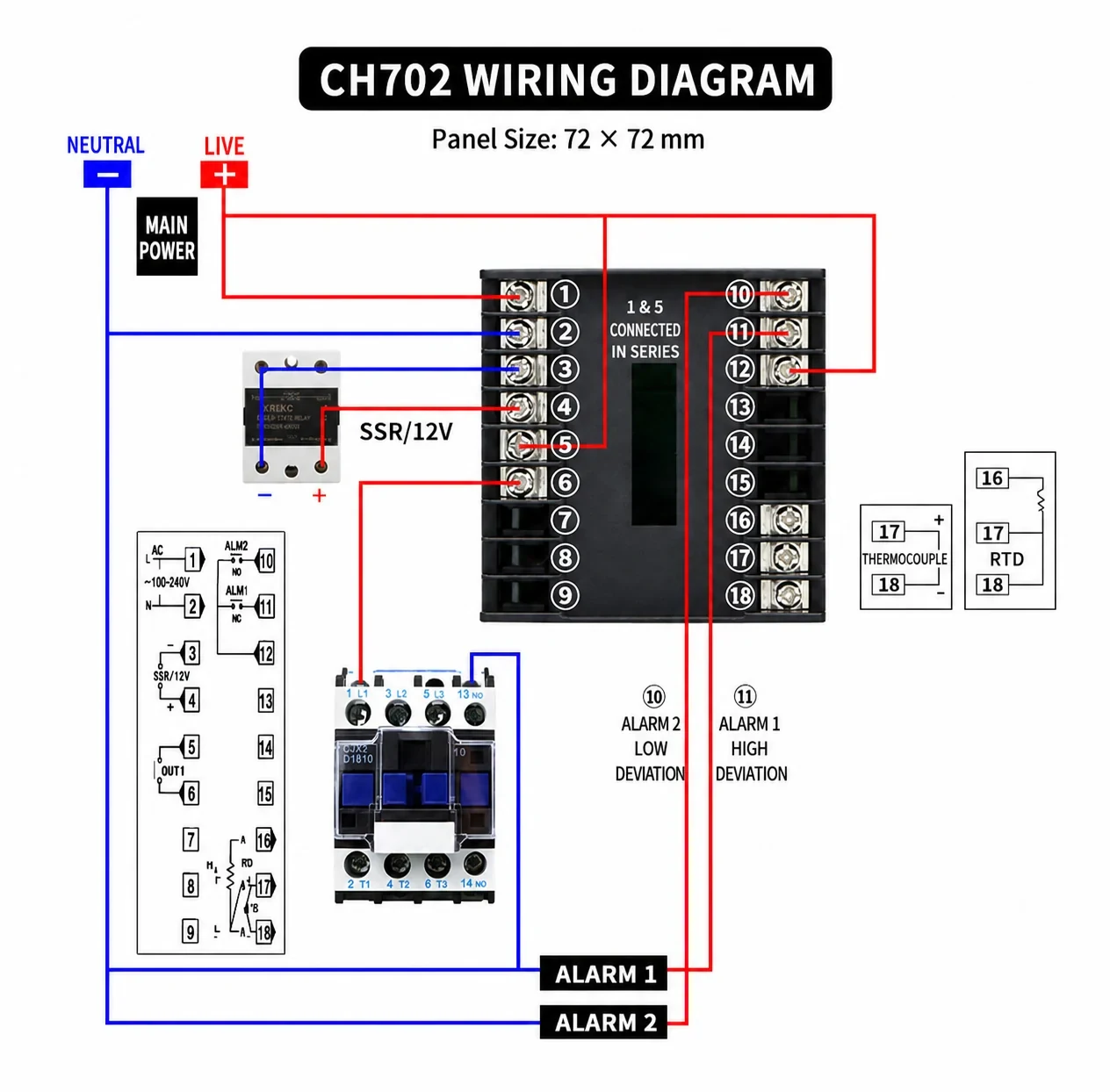
The CH702 uses terminals 1 and 2 for controller power, terminals 3 (–) and 4 (+) for SSR drive, and terminals 5 and 6 for relay OUT1. Its alarm and sensor terminals differ from the 12-terminal models: Alarm 2 uses terminals 10–12, Alarm 1 uses 11–12, a thermocouple uses 17 (+) and 18 (–), and a three-wire Pt100 uses 16, 17 and 18.
Method A — Relay output with an AC contactor
Use this method when the controller has a relay output and the heating load is switched by an external AC contactor. The controller relay switches only the contactor coil; the contactor’s main contacts switch the heater current.
- Isolate both the control and heater power circuits.
- Connect the controller supply to terminals 1 and 2 according to the unit label.
- Feed the correctly rated contactor-coil control circuit through OUT1 terminals 5 and 6 as shown in the applicable diagram.
- Connect the other side of the coil to its required control supply return.
- Route the heater power through the contactor’s main contacts, not through the controller terminals.
- Install suitable branch protection, isolation and protective earth for the heater and enclosure.
- Confirm that the coil voltage matches the control voltage and that the contactor is rated for the heater load and expected switching frequency.
The relay output is a switching contact, not a power source. External voltage must be provided by the correctly designed coil circuit.
Method B — SSR drive output
Use an SSR-output CH controller when silent, frequent switching is required for PID time-proportioning control. The controller’s SSR terminals operate the SSR input; they do not supply heater power.
- Isolate the controller and heater supplies.
- Connect the controller supply to terminals 1 and 2.
- Connect SSR drive negative to terminal 3 and positive to terminal 4.
- Wire the SSR load terminals in series with the heater power circuit according to the SSR manufacturer’s instructions.
- Select an SSR with a compatible input range and adequate output voltage and current ratings.
- Mount the SSR on a correctly sized heat sink with suitable thermal compound or interface material.
- Provide overcurrent protection and, where the application requires it, independent over-temperature protection and an isolation contactor.
Never reverse the SSR input polarity. Do not connect the heater directly to terminals 3 and 4.
Sensor wiring
Thermocouple
For CH102, CH402 and CH902, connect thermocouple positive to terminal 11 and negative to terminal 12. For CH702, connect positive to 17 and negative to 18.
Use the correct thermocouple extension cable for the selected sensor type. Thermocouple color codes vary by standard and country, so identify polarity from the probe documentation rather than relying only on insulation color. If the displayed temperature falls when the probe is heated, isolate the system and recheck polarity and controller input settings.
Three-wire Pt100 RTD
For CH102, CH402 and CH902, connect the Pt100 to terminals 10, 11 and 12. For CH702, use terminals 16, 17 and 18. Follow the A/B/B or equivalent markings on the controller diagram and sensor datasheet. The two same-side RTD leads normally connect to the two corresponding B terminals.
Do not connect a thermocouple and Pt100 at the same time. After wiring, configure the controller’s input parameter for the installed sensor.
Alarm outputs
Alarm outputs are dry contacts intended for an external indication or interlock circuit within their published ratings. In the diagrams, Alarm 1 is used as a high-deviation alarm and Alarm 2 as a low-deviation alarm. The actual behavior depends on the configured alarm mode and alarm value.
Use an interposing relay if a buzzer, lamp or downstream device exceeds the alarm-contact rating. A software alarm should not be the only protection against a hazardous over-temperature condition; use an independent safety limit where required by the risk assessment or applicable standard.
First-power commissioning checklist
- Confirm the model and output option against the order code and label.
- Confirm supply voltage and terminals 1–2 before energizing.
- Verify that the sensor type, terminal numbers and polarity match the controller configuration.
- Verify that only the intended control output method is wired.
- Check contactor coil voltage or SSR input compatibility.
- Check heater current, switching-device rating, heat sink, fuses or breakers, conductor sizes and protective earth.
- Confirm all terminals are tight and no exposed strands can bridge adjacent terminals.
- Set a low, safe test setpoint and conservative alarm values.
- Energize the controller and compare the displayed process value with the expected ambient or process temperature.
- Raise the setpoint slightly and verify the output indicator and contactor or SSR operation.
- Observe at least one complete heating cycle. Confirm that heating stops as expected and that temperature remains under control.
- Run PID auto-tuning only under safe, representative process conditions and with supervision.
Troubleshooting
The controller does not power on
- Isolate the circuit and measure the incoming voltage with an appropriate instrument.
- Confirm that power is connected to terminals 1 and 2 and matches the controller label.
- Check upstream protection, disconnects, terminal tightness and conductor continuity.
The displayed temperature is incorrect
- Confirm that the configured input type matches the installed thermocouple or Pt100.
- Check thermocouple polarity or the three-wire Pt100 arrangement.
- Inspect for loose joints, incorrect extension cable, grounded-junction issues or electrical noise.
- Route sensor conductors away from contactors, SSR load cables, motors and heater wiring.
The output indicator is on, but the heater remains cold
- For relay control, check the OUT1 contact circuit, contactor coil voltage and main contacts.
- For SSR control, check the 3/4 polarity, SSR input indicator, load-side voltage and heat-sink installation.
- Check the heater, over-temperature limiter, fuses, breakers and power wiring independently.
The contactor chatters
- Confirm that its coil voltage matches the control supply.
- Check for low voltage, loose connections or an unsuitable control mode.
- A mechanical contactor should not be driven at the rapid cycle rate normally used for an SSR. Adjust the output cycle time appropriately for relay/contactor control.
Temperature overshoots the setpoint
- Confirm sensor location and thermal contact.
- Run PID auto-tuning under representative load conditions.
- Check that heater capacity is appropriate for the process.
- Confirm that the output type and control-cycle setting match the switching device.
Frequently asked questions
Are CH102, CH402, CH702 and CH902 wired identically?
They use the same basic functions, but CH702 has different alarm and sensor terminal numbers. Always use the diagram for the exact model.
Can the controller switch a heater directly?
The diagrams on this page show an external AC contactor or SSR. This is the preferred arrangement for industrial heater loads. Do not route heater current through the controller unless the exact relay rating, load type and application design explicitly allow it.
Can I use both relay and SSR outputs at the same time?
Not unless the complete model code and manufacturer documentation explicitly state that both outputs are available and independently usable. Select the wiring method that matches the ordered output option.
Which sensor inputs are supported?
The CH Series product range supports common thermocouple and Pt100 input options. The exact available types depend on the ordered configuration and parameter settings. Confirm the model label and input menu before connecting a sensor.
Why should an SSR use a heat sink?
An SSR produces heat while carrying current. Without adequate heat dissipation, its internal temperature can rise beyond its rating and cause early failure. Size the SSR and heat sink for the actual load and enclosure temperature.
Need help selecting a CH Series controller?
When requesting technical support or a quotation, send the complete model code, supply voltage, sensor type, heater voltage and power, preferred output method, alarm requirements and a photo of the existing wiring. Strong Electric can help confirm the appropriate CH Series configuration, sensor and switching device before installation.
Explore the CH Series PID temperature controller or contact Strong Electric for model-selection and wiring support.