
Technical Guides · 2026-08-25
TEL96-9001 Temperature Controller Wiring Guide: Direct Heater and AC Contactor Methods
Terminal-by-terminal wiring for the TEL96-9001 ON/OFF temperature controller: K-type thermocouple connection, direct heater switching up to 1500 W, AC contactor control, 220 VAC to 380 VAC supply change, commissioning checklist and troubleshooting.
The TEL96-9001 is an industrial temperature controller for simple heating applications using a K-type thermocouple and a relay dry-contact output. It operates from 220/380 VAC, 50/60 Hz, and uses ON/OFF control with a 2°C differential.
This guide explains the published terminal connections, shows when the controller may switch a heating element directly, and shows when an external AC contactor should be used. Wiring must be completed by a qualified electrician with the supply isolated. More models are listed under temperature controllers.
Important: Check the model label and the wiring diagram supplied with the controller before installation. Product variants or later production revisions may use different connections. The supplied diagram and product markings take priority over this guide.
TEL96-9001 specifications
| Item | Specification |
| Model | TEL96-9001 |
| Power supply | 220/380 VAC, 50/60 Hz |
| Measurement accuracy | Digital display: ±1.0% FS; pointer: ±2.5% FS |
| Control method | ON/OFF control with 2°C differential |
| Sensor input | K-type thermocouple |
| Control output | Relay output, voltage-free contact |
| Operating temperature | 0°C to 50°C |
| Operating humidity | 30% to 85% RH |
| Atmosphere | Non-corrosive gas |
Before wiring
- Disconnect, lock out, and verify the absence of voltage before touching any terminal.
- Confirm whether the incoming supply is 220 VAC or 380 VAC.
- Confirm that the sensor is a K-type thermocouple.
- Keep thermocouple wiring separated from mains and heater conductors to reduce electrical interference.
- Use conductor sizes, insulation ratings, overcurrent protection, earthing, enclosure, and contactor ratings suitable for the actual supply and load.
- Tighten terminals securely and fit guards or an enclosure so live parts cannot be touched.
- Do not use the controller in a corrosive atmosphere or outside the stated temperature and humidity range.
Key terminal connections shown in the supplied diagrams
| Connection | Terminal(s) | Note |
| K-type thermocouple | 5 and 6 | Diagram shows blue lead to 5 and red lead to 6. Confirm the supplied probe and polarity markings before energizing. |
| Relay output | 2 and 3 | Voltage-free switching contact shown as OUT in the electrical diagram. |
| 220 VAC controller supply | 7 and 8 | Use the exact arrangement in the supplied 220 VAC wiring diagram. |
| 380 VAC controller supply | 7 and 9 | Move all wire(s) installed on terminal 8 to terminal 9; other terminal wiring remains unchanged, as stated in the supplied diagram. |
| Required link in the illustrated arrangements | 3 and 9 | Fit the short link exactly as shown in the applicable diagram. |
Do not generalize from wire color alone. Identify live, neutral, phases, and thermocouple polarity using the equipment markings, the supplied diagram, and appropriate test instruments.
Method 1: Direct connection to a heating element
Use the direct-load arrangement only when the heating element is a compatible resistive load and its rated power does not exceed 1500 W, as stated on the supplied diagram. If the load exceeds this limit, or if its switching duty is unsuitable for the internal relay, use the AC contactor method below.
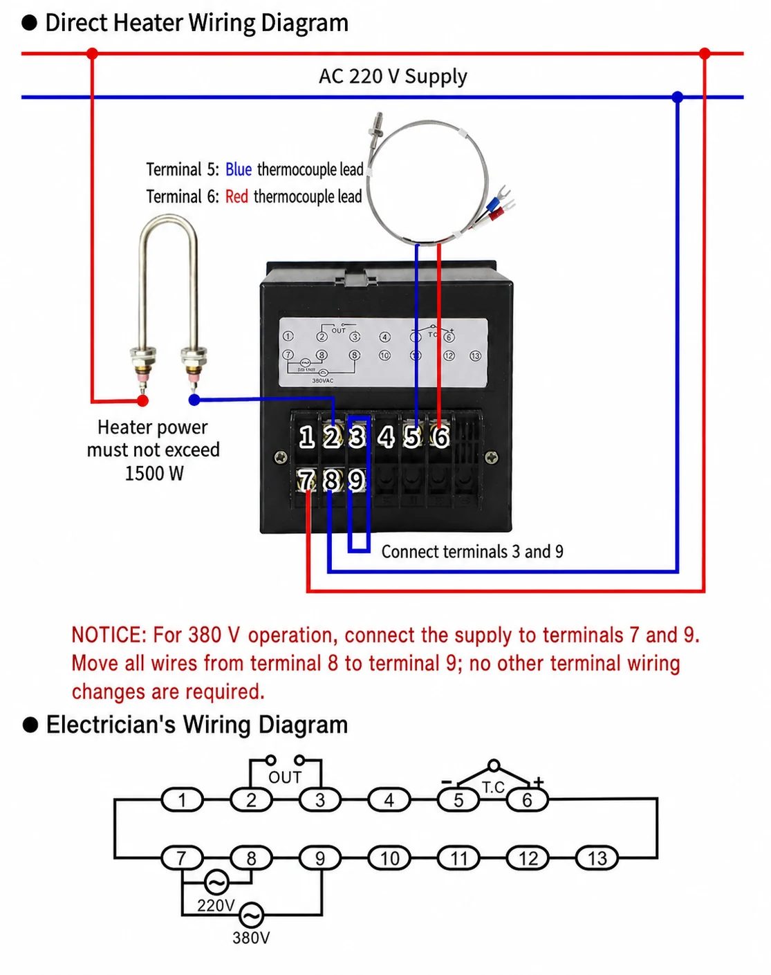
Direct-load wiring sequence
- Isolate and verify the supply is dead.
- Connect the K-type thermocouple to terminals 5 and 6 in the polarity shown in the supplied diagram.
- Fit the short link between terminals 3 and 9 as shown.
- For a 220 VAC supply, connect the controller supply to terminals 7 and 8 exactly as illustrated.
- Connect the heating element through the controller relay circuit exactly as illustrated. Do not exceed 1500 W.
- Fit the required protective earth to the heater sheath, machine frame, and metal enclosure where applicable. Protective earth is not shown in the simplified product diagram.
- Check every termination, replace all covers, and then energize for commissioning.
Method 2: Switching the heater through an AC contactor
Use an AC contactor when the heater load is above the direct-switching limit, when the application requires a suitably rated external switching device, or when control-panel practice calls for separation between the controller relay and the heater power circuit.
In this arrangement, the TEL96-9001 relay switches the contactor coil. The contactor’s power contacts switch the heating load. The contactor coil voltage must match its control supply, and the contactor contacts must be rated for the heater voltage, current, load type, and switching duty.
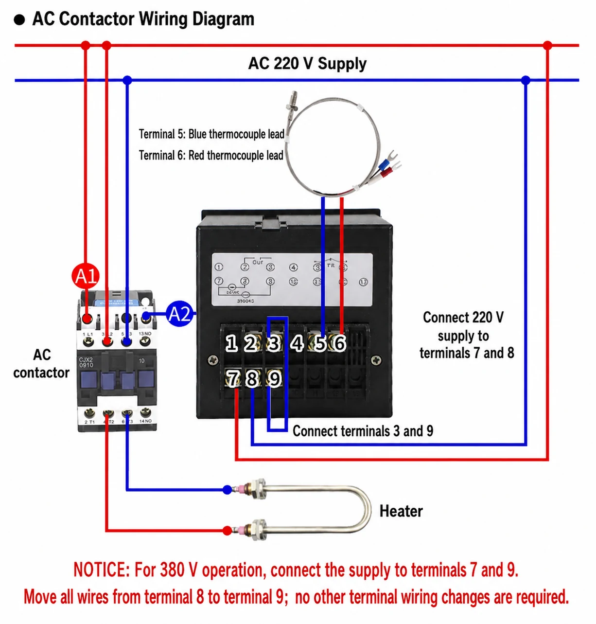
Contactor wiring sequence
- Isolate both the controller supply and the heater power circuit, then verify they are dead.
- Connect the K-type thermocouple to terminals 5 and 6 in the polarity shown.
- Fit the short link between terminals 3 and 9 as shown.
- Connect the 220 VAC controller supply to terminals 7 and 8 exactly as illustrated.
- Wire the controller relay circuit to contactor coil terminals A1 and A2 exactly as shown in the supplied diagram.
- Route the heater power circuit through the contactor’s appropriately rated main contacts. Do not route heater current through the contactor coil circuit.
- Verify coil voltage, contact ratings, protective devices, conductor sizes, earthing, and terminal tightness before energizing.
Changing the controller supply from 220 VAC to 380 VAC
The supplied diagram states that, for 380 VAC operation, the supply connection is made at terminals 7 and 9. Move all wire(s) fitted to terminal 8 onto terminal 9; wiring on the other terminals remains unchanged.
Because 380 VAC is hazardous and supply systems differ by installation, a qualified electrician must confirm the phase arrangement and available voltage before making this change. Never assume that a conductor is neutral or a particular phase based only on its color.
Commissioning checklist
- Confirm the controller model is TEL96-9001 and the selected supply connection matches the measured supply voltage.
- Confirm the K-type thermocouple is connected to terminals 5 and 6 with the correct polarity.
- Confirm the 3–9 link and all load or contactor connections match the applicable supplied diagram.
- Confirm a direct-connected heater is no more than 1500 W.
- For contactor control, confirm the coil voltage and contact ratings match the circuit.
- Confirm protective earth and overcurrent protection are installed as required.
- Set a low, safe test temperature before first energization.
- Energize the controller and compare the displayed temperature with the expected ambient or process temperature.
- Raise the setpoint slightly and verify that the relay or contactor energizes and the heater begins warming.
- Lower the setpoint and verify that the output releases. Observe at least one complete heating cycle before normal operation.
Troubleshooting
The controller does not power on
- Isolate the supply and verify the incoming voltage.
- Check that 220 VAC uses terminals 7 and 8, or that 380 VAC uses terminals 7 and 9, according to the supplied diagram.
- Check upstream protection, conductor continuity, and terminal tightness.
The temperature reading is incorrect or moves in the wrong direction
- Confirm that the sensor is a K-type thermocouple.
- Check the terminal 5 and 6 connections and thermocouple polarity.
- Check for loose joints, unsuitable extension cable, electrical noise, or contact between the probe and an unintended live conductor.
The controller indicates heating, but the heater remains cold
- Isolate the circuit before testing continuity.
- Check the relay path at terminals 2 and 3 and the required 3–9 link against the applicable diagram.
- In a contactor installation, check whether the coil energizes and whether the main contacts close.
- Check the heater, contactor, protective devices, and power wiring independently.
The contactor chatters
- Verify that the contactor coil voltage matches the control circuit.
- Check for low or unstable voltage and loose coil connections.
- Remember that the TEL96-9001 uses ON/OFF control with a 2°C differential; select a contactor suitable for the expected switching duty.
The temperature overshoots the setpoint
- Some overshoot is possible in ON/OFF systems because the heater and process retain heat after the output switches off.
- Improve sensor placement and thermal contact, reduce heater power where appropriate, and verify that the application is suitable for 2°C differential control.
Frequently asked questions
What sensor does the TEL96-9001 use?
The published specification identifies a K-type thermocouple input. Do not connect a Pt100 RTD or another thermocouple type unless the exact product label and manufacturer documentation explicitly support it.
Can the TEL96-9001 switch a heater directly?
The supplied direct-wiring diagram limits the heating element to 1500 W. Use an appropriately rated external AC contactor when the load is above that limit or when required by the application.
Is the output a voltage signal?
No. The published specification describes a relay output with a voltage-free, or dry, contact. The external circuit supplies the voltage being switched.
Does the TEL96-9001 use PID control?
No PID function is stated in the supplied specification. The controller is identified as an ON/OFF controller with a 2°C differential.
How is 380 VAC connected?
The supplied diagram states that the supply uses terminals 7 and 9 for 380 VAC. It also instructs the installer to move all wire(s) from terminal 8 to terminal 9 while leaving other terminal wiring unchanged.
Need help confirming the wiring?
Send Strong Electric a clear photo of the TEL96-9001 label and terminal block, together with the supply voltage, heater voltage and wattage, contactor coil voltage, and thermocouple type. We can help confirm the appropriate arrangement before commissioning.